try here to explain the process I followed to set the operation and the slack of the axes of change.
First you'll ride all bearings and seals in semicárteres before mounting. Thus
heat the crankcase in an oven at 160 º C. If no oven, candle had been placed with a torch as evenly as possible throughout the crankcase. Beware of the flames and aluminum. This is not advised and can overheat, melting.
A hot time (the test droplet Water is crucial: if the one drop on aluminum sizzles and evaporates immediately, it's OK) place yourself in hand (if possible) all the bearings in their housings.
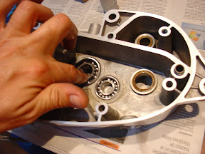
same for seals and bronze bushings.

Mounting change gears.
explain here how to assemble the different gears of change in their axis and with each other, so that they understand its functioning as placing in the crankcase when the engine let's ride definitely. We shall see.
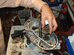
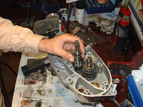
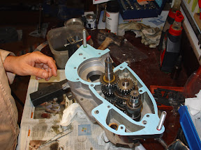
First place the primary axis (the clutch transmits it motor shaft rotation by the extreme left or above in the photo) in conical bearing housing right crankcase. We note that the main shaft is fitted and united with him the first speed gear.

Below secondary axis (this reflects the movement of the primary through the gears and the pinion moves in the right side) is where you place any and / or necessary adjustment spacers . From time to place the same obtained in the disassembly.

We insert the output shaft through the bearing and seal that underneath. Important spread it with engine oil seal lips before inserting the shaft, and above all try not to damage the seal lips with grooves and / or threads of the shaft.

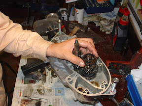
rode the 1st gear pinion on the secondary. This gear rotates freely around the axis, and derives its motion through the pinion 1 st of the primary. That is, if the clutch motor transmits motion to the primary axis, that its sprockets (which rotates all sympathetic to him) and their corresponding sprockets spin faced in the shaft. These gears rotate freely around the shaft, each to his own speed.
We placed the cuff baladeur or 1 ª -2 ª. We note that has a groove which engages the pinion side pins 1 st, plus a perimeter groove where you insert the selector fork that moves from side to side. In the lateral grooves also inserted pins 2 nd pinion to be mounted on top, as it moves the sleeve to one side or another of the change.
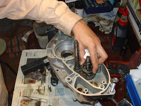
We have seen that with the bike in gear, main shaft rotates and with it his pinions, so that the sprockets sub crazy spin around this axis. When moving the sleeve 1 ª -2 ª up some speed gear (pinion fitting lugs corresponding grooves in their side) said sleeve will rotate. Now if only we connect the sleeve with the shaft to rotate it as well.
That gets into the Impala engine with three cylindrical pins that are inserted in separate grooves in the shaft and holding him to the cuff.
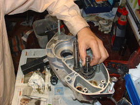
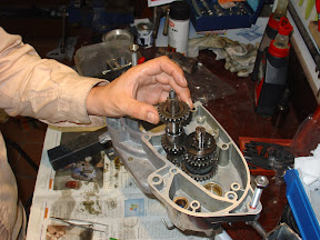
These keys also perform the function of separating the sprockets of 1 st and 2 nd in the shaft. Then insert the pinion 2 nd ...

... and we see that we have a set of two gears are separated by a fixed distance (the length of the keys) and an intermediate sleeve, with the shaft, which can engage one or other gear, as well as the middle position (neutral) .
pinion now placed 2 nd in the primary, which rest on an elastic ring that we will have taken the precaution of changing a new one. For what it costs ...

The way to keep it attached to the pinion shaft is also using cylindrical keys.

now proceed with the other pair of speed (3 rd and 4 th) that follow a similar pattern. We set the pinion
3 rd in the secondary ...

... and its counterpart in the primary, snapping it into the keys, to rotate with the shaft.

continue getting more keys in the primary ...

... and a ring that will keep us apart sprockets 3 rd and 4 th.
We return to the secondary, where we set the sliding sleeve 3 rd -4 th ...
... and their corresponding keys to make your turn is integral with the shaft.

now mounted pinion 4 th in the primary, snapping it into the keys ...
... and its counterpart in the secondary free tour.

Finally we just put the spacers on the left end of the shaft. Remember that the child takes them on the right.
The only thing that we need to function change is the selector drum with their forks. But with the primary and secondary mounted there is no way to insert. In this way, we will draw the two axes with pine nuts as a whole, will assemble outside the housing drum selector (selector forks inserted in the grooves of the sliding sleeve perimeter of the secondary) and remount the crankcase three axes at once as a whole. A method of several potential.
clearance of the axes of change.
Close the left cover on the right, after placement of the two centering sleeves, and the board will use in final assembly. If we do not mount the crankshaft must fit perfectly with the two halves without any effort.
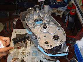
We place through screws (here we can save to put the rings not broken) and we press to consciousness, ie, close the letter as final assembly.
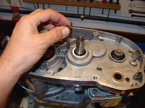
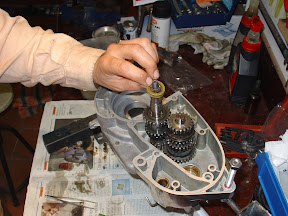
now check the longitudinal movement of each of the three axes (primary and barrel selector on the left side, secondary on the right) ...
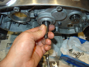
... and measure the displacement total of each one.

Montesa According to the manual of the 70 that runs through the network, this clearance must be 1 or 2 tenths of a millimeter (0.1 - 0.2 mm). I guess the reference is good.
Now, knowing the displacement we have in each axis, we will open the motor and add washers or we will draw the adjustment as appropriate in each one, to leave the required final clearance. Needless
comment that we will use closed crankcase to verify the correct operation and gear speeds. It is therefore worthwhile to present the screw with spring and retaining lug drum switch at the rear of the engine, as this is where we set the switch position when it is supposed to engage each gear.
0 comments:
Post a Comment