Motor Mount - Mounting Components speed selection
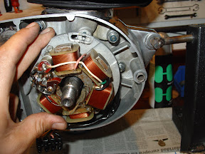
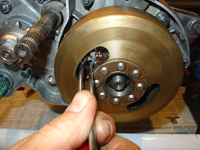
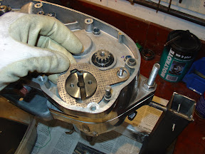
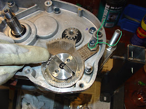
To begin to mount selector , we orientate the axis of the guide so that the offset of the tabs is in the position shown in the photo, that is, the tabs are slightly above the center of rotation.

We set up the panel assembly. Its function is to shrink the tabs inward as you turn the dial.
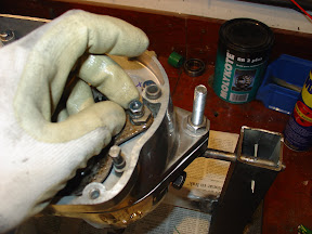
inserted the eccentric nut plate control (turning one or the other side of the nut relative position on the selector plate varies slightly) ...

... and its washer and retaining nut.
We
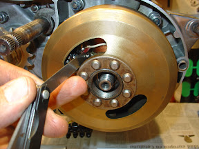
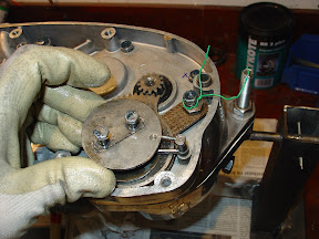
above the second plate so that the shaft engranecon selector drum. The correct way is that the mark on the plate matches the point marked on the shaft. In this position, the gearbox in neutral (check).
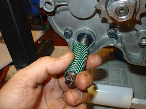
Note the green wire nut that we fitted earlier. It's an idea a friend gave me that as the devil knows more for being old than by the devil. Green (or red, or blue or whatever) means mounted nut but not tight. Much more useful than it seems. 
two tabs are inserted with the spring inside, in the position shown. This is the correct position to neutral.
We put up the whole spring return selector shaft ...
... tightening screws.
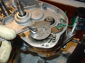
Now is the time to "play" with the change, meshing gears up and down, seeing that everything works properly (we shift the lever while turning the main shaft going to the other hand). Used to regulate the position of the bottom plate with eccentric nut (marked with the green wire) to get smoother and more precise as possible of the change. When we find your ideal position, I squeezed the nut.
With all mounted and operating properly, do not forget to fold the tabs holding the nuts on the spring return selector shaft.
 primary Transimisión
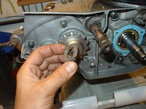
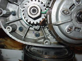
 The primary transmission sprocket crank is attached to it by recess in the tapered shaft. There are no pins or grooves of any kind. To ensure proper anchorage, clean up well before the cone axis of the crankshaft and inside the pinion with a good degreaser (alcohol, for example).

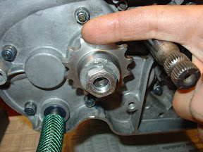
We insert the pinion
...

... washer and nut.
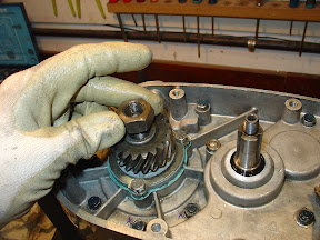 Clutch
 We put the clutch on the output shaft of the change, embedding its outdoor gear helical gear pinion shaft. This gear is what sets the primary drive motor.
We insert the cap on the shaft ...
... and the three keys to retention.
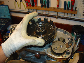
We put the whole clutch hub ...
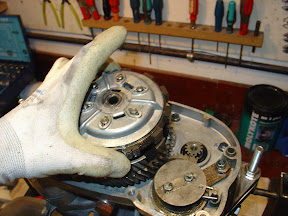
... above the washer and retaining nut ...

... and the nut itself.

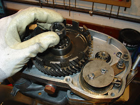
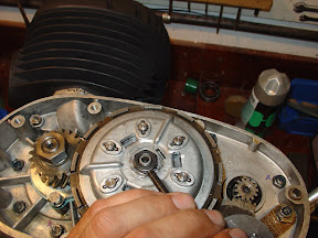
now placed three springs retention of records. These springs assure us that the club is always pressed against the bell in a sense, without giving undesirable rattling.

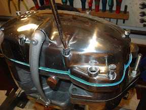
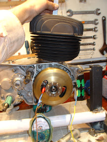
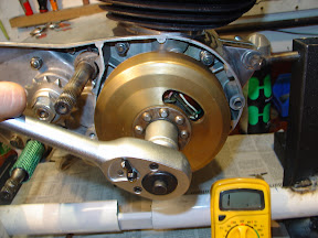
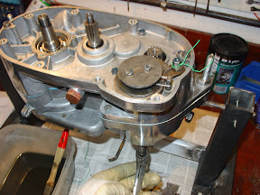
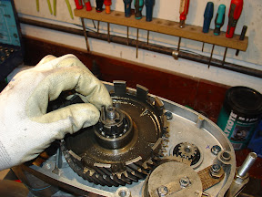
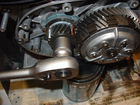
This is the set of primary drive and clutch fitted. You can see the two green wires in the nuts, which indicate that we lack tighten yet.
can use to tighten a euro cent coin (copper), a cloth or any soft material between the primary transmission gears. The idea of \u200b\u200bcloth given to me by Julian, and the currency of John Milan, Milan Workshop.
tightened with a wrench clutch nut. I said with a key, no pneumatic guns, which will thread (I say this from experience). It is a very narrow nut, and has few threads. But if you want to try, no problem. The shaft is much harder nut soft, and what will joderéis threads of the nut and not the shaft.
By the way, the thread is right (normal).

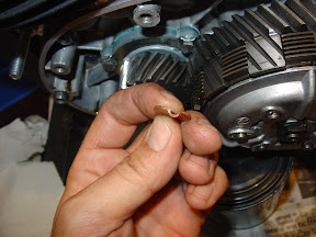
Do the same with the nut on the crankshaft output gear, changing the currency retention of transmission from the bottom up.
This is the currency after the operation. Another cost more to add to the restoration ... ,-D
pin We turned the nut holding the clutch.
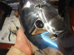
 left engine cover
 Mount shaft seal clutch lever.
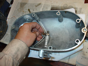
Insert the shaft in its housing (with the lips of oiled seal skins Non)

The interior insert the spacer washer ...

... Clutch pusher latch ...
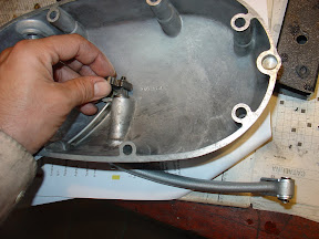
... and washer and retaining nut.

now mounted pusher piston clutch, spread with a little fat to keep from falling off its seat when the lid upside down to revolve with the engine mount.
place the spider clutch putter, centering caps and a new cover gasket ...

... and put the lid on their site ...
... After assembling and tightening the screws.