up to Keep Trick-Parameter Height MKs heavy ...
Hello, this morning, walking around RCGroups, I found this:
"... I'm Probably Not the first to mention it But The best Changing place to start paramters When You Increase the weight of your MK is the "Z-Acc Wirkung."
When you Increase this parameter the Mikrokopter Will Be Influenced more by the Z axis Accelerometers Movement in combination with the barometric pressure. Heavier On May Mikrokopters you want to Increase this value - try values \u200b\u200bfrom ~ 2 to 8, I Have Heard events people report values \u200b\u200bof near 20 on Heavier MK's. Key thing is to experiment - put the parameters on a poti and See What works best for you. "
That is, if you do not work well MAINTAIN HEIGHT, and you have a MK a little heavy, try to raise the value parameter "Z-Acc Wirkung" to 5, 6, 7 or 8 and try to see how it goes, Greetings!
Tuesday, March 31, 2009
Wednesday, March 25, 2009
Foot Stepped On By Stiletto
4 hours to 0.5 Volt - PC Power Supply amended


EXERCISE WORKSHOP "On the table," Taller 99 , Chile
Ignacia Mesa / Etching-I (Etching)


Ignacia Mesa / Engraving - II (Micropunto / Aquatint)


15x increase the metal exposed for 4 hours continuously at 0.5 Volt - The Etching lines are not lost, are kept clean and accurate.

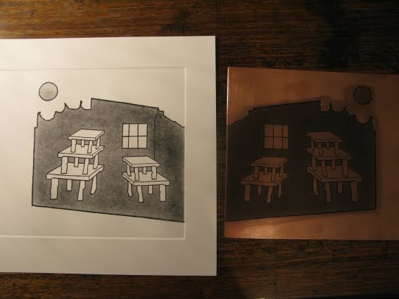

EXERCISE WORKSHOP "On the table," Taller 99 , Chile
Ignacia Mesa / Etching-I (Etching)


Stage I: drawing thick lines Drawing on traditional varnish exposed to 0.5 Volt for 4 continuous hours .
Results: the engraved line is very clean and precise. Traditional protective varnish rose in some places, for which we used shellac, which was more effective.
Results: the engraved line is very clean and precise. Traditional protective varnish rose in some places, for which we used shellac, which was more effective.
Ignacia Mesa / Engraving - II (Micropunto / Aquatint)


Stage II: Reserve white traditional varnish with shellac and then exposed to 0.5 Volt for 4 continuous hours.
Results: black is not achieved, it is necessary to place the iron in the electrolytic tank for longer hours.
Results: black is not achieved, it is necessary to place the iron in the electrolytic tank for longer hours.
Tuesday, March 24, 2009
What Happens After Puppy Takes Worm Medicine
What are the main parameters MKTOOL?
A brief explanation for those who want to keep trying different parameters in the MKTool, this is what makes each of them:
A brief explanation for those who want to keep trying different parameters in the MKTool, this is what makes each of them:
Nick / Roll P-Anteil
With a low value, more control "spongy "(values \u200b\u200b2-3)
With a high value, more agile MK (value 4)
Nick / Role D-Anteil
With a low, slow reactions but soft (values \u200b\u200baround 4)
With a high value, strong reactions to rapid movements of the sticks (values \u200b\u200baround 8)
Valued low, slow turns on itself (value approx. 6)
With a high value, quick turns (value approx. 12)
With too low, we have control on the MK (low normal with control, 80)
With a high value, rapid stabilization reactions (value approx. 100) Gyro I-Anteil
With a low, weak stabilization responses MK very sensitive to wind (120)  With a high value, high stability, more wind resistant (value approx. 140-150)
Best Mount And Blade Defeating
for hands with the welder ...
Here I put the list all components of a FC 1.3, in case one is encouraged to assemble parts of the plate that we can bring clean, BUT you have to solder SMD (my escapes me that for my pulse hehe): http://
www.reichelt.de/?ACTION=20; AWKID = 134869; PROVID = 2084
Other than that, because I think you need also plate and 3
Murata gyroscopes
Hale, if there are any brave do tell us if you need that prompted the board or the gyros, tell me please greetings!
Oakes & Nichols Funeral
Spanish Wiki Possible creation of the MK
Hi, I'm pondering whether to blog this format or the Wiki, what do you think? The
Wiki I have started to create what you have here:
Take a look, I find it easier to bring a better structure check, just in case, sign also that, cheers! Alberto
Hi, I'm pondering whether to blog this format or the Wiki, what do you think? The
Wiki I have started to create what you have here:
Take a look, I find it easier to bring a better structure check, just in case, sign also that, cheers! Alberto
Sunday, March 22, 2009
How Long Does A Co2 Fire Extinguisher Last
Introduction
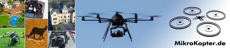
The Mikrokopter was created by Holger Buss and Ingo Busker in Germany for two or three years.
is a very electronic cuatricóptero by allowing it very easy to fly and very stable.
comprises a cross-shaped frame with a brushless motor at each corner. There are various chassis sizes, the most common are the MK-40, with 40 cm of wheelbase of other opposites that propellers mounted 10x4, 5, and the MK-50, with 50cm wheelbase of engines, propellers 12x4, 5.
are 4 motors, controlled by 4 special drives, controlled by a single I2C bus.
 central plate called FlightCtrl (FC), is responsible for giving orders to the other based on various sensors and gyroscopes, to maintain the horizontal, or allow the Mikrokopter (MK) obey the orders from our station.
The FC also mounted a height sensor, which allows us to enable the maintenance of a constant height automatically.
All parameters are modified by the program MKTool from a PC, which binds to MK by a programmer named MKUSB, which works through USB as its name suggests.
Apart from the basic kit included in the later plates can add 3 more: NavyCtrl (NC), the MKGPS (MG) and MK3MAG (MM). With these 3 plates have the possibility to maintain the current position of MK in air (even struggling against the wind), and to activate the MK will return to the starting position ("back home").
 MK kits need 10-12 hours to fit, and require a basic skills-average soldering (many components are already soldiers, but you have to solder cables, capacitors, height sensor and some other things.)
MK can not be used for gainful activity because of a design is copyrighted by Holger Buss and Ingo Busker, but allows use by either an amateur way.
There is a great community around MK to continuously develop improvements, new firmware, new chassis, etc, with the glue that 80% are Germans writing in German, but with sites like this, or Forum of
www.aeromodelismovirtual.com
more and more information in English. 
. 
You are invited to provide any item on this blog, Send these to
The Mikrokopter was created by Holger Buss and Ingo Busker in Germany for two or three years.
is a very electronic cuatricóptero by allowing it very easy to fly and very stable.
comprises a cross-shaped frame with a brushless motor at each corner. There are various chassis sizes, the most common are the MK-40, with 40 cm of wheelbase of other opposites that propellers mounted 10x4, 5, and the MK-50, with 50cm wheelbase of engines, propellers 12x4, 5.
are 4 motors, controlled by 4 special drives, controlled by a single I2C bus.
The FC also mounted a height sensor, which allows us to enable the maintenance of a constant height automatically.
All parameters are modified by the program MKTool from a PC, which binds to MK by a programmer named MKUSB, which works through USB as its name suggests.
Apart from the basic kit included in the later plates can add 3 more: NavyCtrl (NC), the MKGPS (MG) and MK3MAG (MM). With these 3 plates have the possibility to maintain the current position of MK in air (even struggling against the wind), and to activate the MK will return to the starting position ("back home").
MK can not be used for gainful activity because of a design is copyrighted by Holger Buss and Ingo Busker, but allows use by either an amateur way.
There is a great community around MK to continuously develop improvements, new firmware, new chassis, etc, with the glue that 80% are Germans writing in German, but with sites like this, or Forum of
www.aeromodelismovirtual.com
more and more information in English.
We have created the English manuals that are available for free download on our website, click here
.
You are invited to provide any item on this blog, Send these to
info@himodel.es
and we will put happy, Greetings! Alberto How Do You Find Fetus Percentile
Sergafa Conversion of Corona RP8D1
RP8D1 Corona Conversion for use in the MK (POR SERGAFA) (fully realized by SERGAFA, thanks!) This is a small tutorial on how to modify the CORONA receiver to extract the signal RP8D1 ppm and can run on our MK. I've seen for various parts of the forum that this receptor appears to have many benefits for what will be flying in FPV, due to its large scope. In this case the CORONA RP8D1 has an integrated microprocessor called ATMEL MEGA88v. This process is quite complex and full of analog / digital converter and other things that I will not explicar.La point is that in one of his sideburns reached receptor.Esta ppm signal is weak signal and low voltage also fills "noise" (meaning it's not a perfect square wave is filtered), which is fit for the MK.  What I had to do with an oscilloscope is to locate the signal voltaje.En ppm and know their various images you can see the layout of the components of the receiver and the explanation of how the signal achievement ppm.En Figure 1 shows the inside of the receiver and its components, in this case the microprocessor Atmel Mega88v.
Then, when we finish, we joined the Navy to the FC by two flat cables: - One in NavyCtrl-
What I had to do with an oscilloscope is to locate the signal voltaje.En ppm and know their various images you can see the layout of the components of the receiver and the explanation of how the signal achievement ppm.En Figure 1 shows the inside of the receiver and its components, in this case the microprocessor Atmel Mega88v.
Then, when we finish, we joined the Navy to the FC by two flat cables: - One in NavyCtrl-  SV8 and FlightCtrl-
SV1 -
Other among NavyCtrl -SV6-FlightCtrl and SV5
To access
from MKTool ALL PLATES TO CONNECT THE PINES MKUSB "DEBUG" FOR THE NAVY.
INSTALLATION IN
MK VERY IMPORTANT: Place the Navy in a plastic turrets of 3x10 or 3x15 on FCDE connect so that the above is 3 +3 3 +3 HR, and above the 5 +5 5 +5 HR.
Once installed, placed in the MK3GPS MK (united in its socket to the Navy) and GPS (joined the Navy with the cable that comes ready to use.)
SETTING IN
MKTOOL Once you have mounted the HR MK NAVY, the MK3MAG and MKGPS, we start configuring the MKTOOL (Use the latest version).
connected as said above the MKUSB the PC, and then your pin ribbon cable to the "DEBUG" in the NAVY.
You MUST first upgrade the firmware, we take the latest version as always from within MKTOOL (using "UPDATE VERSION-LIST" and "Download") and updated, but in this order:
1 º LA NAVYCTRL (currently the latest firmware is 0.14b) FLIGHCTRL 2 º LA (currently the latest firmware is 0.72p) 3 The MK3MAG (currently the latest firmware 0.21b)
(If you already have that version in one of the plates is not necessary to re-upgrade) (Before you upgrade a board, write down your most important parameters, especially CHANNELS)
Once updated
However, PUT THE CHANNELS (tab "Channels" of the parameters of the FLIGHTCTRL) in their correct values \u200b\u200bto prevent accidents.
In POTI3, we channel our station is a lever 3 positions.
Once we have this, we can set parameters, etc in the MKTOOL.
acting for the new plates, activate first tab the KOMPASS CONFIGURATION SETTINGS and GPS.
NAVY To configure GPS and have two tabs:
TAB 1: BASIC PARAMETERS
(NAVY PHOTO DISPLAY 1)
Put the POTI3 in the first parameter (which we have assigned to a lever 3 position in our station so we value below 0 (good if is between 0 and 20), in the middle approx. 100 (between 20 and 200 served) and up more than 200) (We see this easily with graphics tab "Channels")
If you set it in this way to activate that lever three positions and different behaviors:
1 º LEVER BELOW: KEEP POSITION
2 º LEVER IN THE HEART: THE ACT NO GPS, FREE FLIGHT.
3 º LEVER UP: BACK TO THE POSITION MK "HOME."
The other parameters are:
"GPS GAIN: Define if the MK is more or less faithfully the GPS data. If we put too high, the MK "shake", you should put a potentiometer assigned to free the station and keep trying ... or leave the default value: 100%
"GPS STICK THRESHOLD": If we put a value greater than 0, when we activated the "HOLD POSITION" (POTI3 lever below), we can move slightly MK with the levers of the station and yet when we release levers MK back in the position he was having, while if more levers move comes a time it will move to a new position and will be the new you now hold.
"MIN SAT": The minimum number satélties that should detect the GPS to imprint the "HOME" (house). If we put too high, take a long time to catch but the GPS satellites will be more precise, usually leave the default value: 6
"GPS-P": The higher the value, the more inclined MK right-left controlled movement in GPS. Default: 90
"GPS-I": The higher the value, the more front-back tilt of MK in the movement controlled by GPS. Default: 90
"GPS-D" value, the GPS-controlled movements slower. Default: 90
"GPS ACC": The higher the value, the faster MK reacts with pushing (for a slap us or a gust of wind)
With the new firmware have a second screen parameters:
(NAVY PHOTO DISPLAY 2)
"GPS WIND CORRECTION" turn makes the "BACK HOME", MK fly more directly to the position of "Home", preventing it from being deflected by the wind. Default: 100%.
"SPEED COMPENSATION": When we are in "HOLD POSITION", automatically brakes the MK if he takes a lot of speed to move to the point you want to keep. Default: 100%.
"GPS MAX RADIUS: Create a" virtual fence "circular radius in meters say. This barrier is insurmountable when MK is controlled by the GPS if the GPS managed by MK reaches that barrier, it remains a point of the circle without going over.
We assign the radio a POTI to make it smaller. At most, we can set it to 512 meters. The default value is 100m.
The focus of this "circle" barrier "is in the" House "that the MK was recorded when the GPS satellites and start the engines.
"GPS ANGLE LIMIT": Sets the maximum angle of ascent or descent of MK when controlled by GPS. For example if we put 60 equals 35 ° angle of maximum rise or fall. Default: 20
THE 3 WAYS OF GPS
As said earlier, we have 3 modes of operation GPS:
IMPORTANT: BOTH WAYS TO "HOLD POSITION" AS "BACK HOME", WE HAVE TO BE ON THE "KEEP HEIGHT" TO ASSIGNED TO HANDLE THAT WE HAVE TO WORK WELL AND NOT GO TO THE FLOOR FOR EXAMPLE WHEN THE DEMOS MK homecoming. "
MODE "HOLD POSITION" (also called "Hold Position" or "AID")
begins operation when we mapped the 3-position lever all the way down (or when its value is between 0 and 20)
- is a way to help: if we play NICK levers or ROLL, MK obey us, the pilot takes precedence over maintenance ALC.
- When the MK takes the position to maintain, you will hear a BEEP.
VOID MODE
begins operation with the lever assigned in the central position (when its value is between 20 and 200)
- In this mode, as if we have GPS, do not act.
MODE "back home" (also called "COMING HOME")
begins operation with the lever in the position assigned TOP OF EVERYTHING (when its value is greater than 200)
- The Home location or "Home" is recorded where uproot the other (a Once the GPS satellites have picked up enough)
DANGER: BEFORE YOU TURN BACK TO RISE LEVER HOUSE, WE ACTIVATE THE "KEEP HEIGHT" AND SEE WHAT YOU ARE DOING WELL, IF WE DO THE MK hits the ground ...
0.71C FROM VERSIONS OF THE FC AND 0.12 OF THE NAVY, IT has been simplified: Now we can assign
POTI3 SAME HEIGHT CONTROL
, and "maintenance HEIGHT turns on when PUTTING LEVER UP OR DOWN AT ALL, WITH WHAT TIME TO ACTIVATE THE "HOLD POSITION" OR "BACK HOME", also activates the "KEEP HEIGHT, AND WE CAN SET TO BE ACTIVATED IF THE VALUE OF THE HANDLE IS UNDER 50 AND / OR OVER 180.
OUR FIRST FLIGHT WITH GPS
safe to do a flight using GPS, you must follow these steps:
1 .- Find a very large, without walls, no wires, no people .. .
2 .- Check that the cables are connected between FlightCtrl and Navy
3 .- Turn on and wait:
- The MK beep every second and the GPS led stops flashing (still have not found anything satellites)
- Now the MK still beeps but less volume and starts to blink the LED of GPS (the GPS has found something, but not yet has 6 satellites)
- (In the previous moment, if we move the lever attached to GPS beeps too)
- When you have the GPS satellites to 6 (or those who have put in the parameter "Min Sun"), the MK back to beep and the light of GPS is ¿¿¿??? (If you can tell me what you have tried someone I thank you, it does not know)
4 .- Put the GPS handle NULL MODE (AT CENTER)
5 .- Start engine and wait segundillos
a
6 .- Make a steady around 2 meters for 20-30 seconds until the MK fly well, trim if necessary people awhile 7 .- Top
a bit more and turn the "KEEP HEIGHT" if we have independent GPS lever, giving a little more gas if necessary to maintain altitude.
7 .- GPS LEVER DOWN DOWN to activate the "HOLD POSITION" MK Now keep your position until we act on the levers and aileron (remember that the pilot takes precedence)
8 .- AGAIN PUT THE LEVER IN THE CENTRAL POSITION AND AGAIN FLYING WITHOUT GPS. EYE TO HANDLE GAS, WHICH CAN BE VERY HIGH AND WE HAVE NOTHING TO LOSE MORE GAS PUT THE LEVER IN THE CENTRAL POSITION OF GPS IF WE HAVE THE SAME POTI3 HEIGHT CONTROL ...
9 .- If we had the height control lever in a separate, now to disable the land: Eye LEVER WITH GAS, LIKE WE HAVE PLACED IN THE ABOVE ITEM, TO REMOVE THE CONTROL OF HEIGHT, WILL SURELY QUICK TO REDUCE GAS TO NOT RAISE THE MK ...
More information (in English):
http://www.mikrokopter.com/ ucwiki / en / NaviCtrl
topic
http://forum.mikrokopter.de/-7122. html
Removing the signal receiver ppm CORONA RP8D1 for Mikrokopter
Figure 2 shows the test point from which we extract the signal ppm for future modification and debugging señal.En this point the signal goes through the other side of the plate and provides the circuit Integrated SA606, the qual is covered by an electronic component.
Figure 3 shows enlarged the area of \u200b\u200btest signal as ppm and across the board enters a leg of ATMEL.
Figure 6 are the output pins of the receiver, where one of them, than us we want to connect the signal amplified ppm. Lifting of the circuit that if for no problems with the signal coming out of Atmel MEGA88v. 
I wish someone would dare and I explain how it has gone. Sorry if I explained bad
on occasion and in future I'll be improving interventions. Thanks and any questions on the circuit will not hesitate to


Figure 4 shows a circuit diagram of the circuit we must do to amplify the signal and convert it to a signal that the MK understand and manage correctamente.La explanation circuit is really simple.
The LM393 is a dual circuit speed comparator comparator rápida.Necesitamos this quickly so that we properly manage the signal R2 and R3 resistors salida.Las all they do is create a tension of about 2x input about the (- negative) LM393 circuit. We need to put this tension when compared to the weak signal we ppm of output a filtered signal with a peak voltage sufficient for the resistance R1 MK.La only sets an output voltage to 5V or so . The R3 may vary between a value of 0.670 K and 0.680 K without any problema.Hasta this truth follow me?
I know that for some, all this will seem Chinese and other insurance that is a "mini chapuzilla. But best of times do not know. I hope you help. I will not roll-up or with the intensity nor the long explanation of what makes the LM393 circuit. Figure 5 The pin I have set extracted from a circuit LM393 datasheet for you to know that each pin is and how to connect the resistors.
Figure 6 are the output pins of the receiver, where one of them, than us we want to connect the signal amplified ppm. Lifting of the circuit that if for no problems with the signal coming out of Atmel MEGA88v.
Figure 7 we see the circuit in test mode and as quietly, watching the oscilloscope clearly PPM signal to a level approx 5v Flight Ctrl perfect for MK.
The figure 8 shows the final result. Of course, say that is a bit experimental and highly improved. I hope to do the next circuit with SMD components and be able to insert inside the CORONA receiver.
you can also dispense with the small plate and place the Bakelite air components. Will be smaller. Everything to occupy less space and weight
.I hope to have been helpful for building this small circuit.
components are worth more than 1 euro and do or not depends on what handyman who seais.El LM393 circuit so you can get in stores electronic without complications, even in MDS will be much better to reduce
final.Cuando size it has made in SMD and put some photos.  The truth is that it is not difficult to solder these 4 components and the point of testing
PPM signal is large enough to place a small
I wish someone would dare and I explain how it has gone. Sorry if I explained bad
on occasion and in future I'll be improving interventions.
Thanks and any questions on the circuit will not hesitate to preguntar.Sergafa.
(although I put up, it is clear that this great work we are coming to work every bead is EXCLUSIVELY Sergafa fellow, I've only uploaded the pictures to our server and have copied here, thanks Sergio!)
Wednesday, March 18, 2009
Follando Con Niñas
Manual for MK's Spanish Navy
PLATE MANUAL NAVY-CTRL v.1.1

The NavyCtrl not come with the basic kit.
is a plaque along with the MK3MAG and extends MKGPS the potential of MK, with features like "Hold Position" (hold position) and "Coming Home" (return home).
is still under development, with future firmwares will expand your possibilities for navigation "Waypoints" ("destinations").
The NavyCtrl contains an ARM9 processor, a MicroSD card reader, a socket where you connect the MK3MAG and a socket for future expansion. MOUNT
The NavyCtrl kit there are several components that we weld ourselves
- 1 electrolytic capacitor (C1): EYE THE SOLDIER WITH THE POLES IN THE NAVY
- 1 row of pins 5 +5 (for connecting to the FC Navy) - 1 row of pins 3 +3 (to connect the SPI interface with FC)
- 1 row of pins 5 +5 in DEBUG (THESE ARE NOT INCLUDED WITH THE NAVY, remember to buy separately or that you have used any surplus).
SV1 -
Other among NavyCtrl -SV6-FlightCtrl and SV5
To access
from MKTool ALL PLATES TO CONNECT THE PINES MKUSB "DEBUG" FOR THE NAVY.
INSTALLATION IN
MK VERY IMPORTANT: Place the Navy in a plastic turrets of 3x10 or 3x15 on FCDE connect so that the above is 3 +3 3 +3 HR, and above the 5 +5 5 +5 HR.
Once installed, placed in the MK3GPS MK (united in its socket to the Navy) and GPS (joined the Navy with the cable that comes ready to use.)
SETTING IN
MKTOOL Once you have mounted the HR MK NAVY, the MK3MAG and MKGPS, we start configuring the MKTOOL (Use the latest version).
connected as said above the MKUSB the PC, and then your pin ribbon cable to the "DEBUG" in the NAVY.
You MUST first upgrade the firmware, we take the latest version as always from within MKTOOL (using "UPDATE VERSION-LIST" and "Download") and updated, but in this order:
1 º LA NAVYCTRL (currently the latest firmware is 0.14b) FLIGHCTRL 2 º LA (currently the latest firmware is 0.72p) 3 The MK3MAG (currently the latest firmware 0.21b)
(If you already have that version in one of the plates is not necessary to re-upgrade) (Before you upgrade a board, write down your most important parameters, especially CHANNELS)
Once updated
However, PUT THE CHANNELS (tab "Channels" of the parameters of the FLIGHTCTRL) in their correct values \u200b\u200bto prevent accidents.
In POTI3, we channel our station is a lever 3 positions.
Once we have this, we can set parameters, etc in the MKTOOL.
acting for the new plates, activate first tab the KOMPASS CONFIGURATION SETTINGS and GPS.
NAVY To configure GPS and have two tabs:
TAB 1: BASIC PARAMETERS
(NAVY PHOTO DISPLAY 1)
Put the POTI3 in the first parameter (which we have assigned to a lever 3 position in our station so we value below 0 (good if is between 0 and 20), in the middle approx. 100 (between 20 and 200 served) and up more than 200) (We see this easily with graphics tab "Channels")
If you set it in this way to activate that lever three positions and different behaviors:
1 º LEVER BELOW: KEEP POSITION
2 º LEVER IN THE HEART: THE ACT NO GPS, FREE FLIGHT.
3 º LEVER UP: BACK TO THE POSITION MK "HOME."
The other parameters are:
"GPS GAIN: Define if the MK is more or less faithfully the GPS data. If we put too high, the MK "shake", you should put a potentiometer assigned to free the station and keep trying ... or leave the default value: 100%
"GPS STICK THRESHOLD": If we put a value greater than 0, when we activated the "HOLD POSITION" (POTI3 lever below), we can move slightly MK with the levers of the station and yet when we release levers MK back in the position he was having, while if more levers move comes a time it will move to a new position and will be the new you now hold.
"MIN SAT": The minimum number satélties that should detect the GPS to imprint the "HOME" (house). If we put too high, take a long time to catch but the GPS satellites will be more precise, usually leave the default value: 6
"GPS-P": The higher the value, the more inclined MK right-left controlled movement in GPS. Default: 90
"GPS-I": The higher the value, the more front-back tilt of MK in the movement controlled by GPS. Default: 90
"GPS-D" value, the GPS-controlled movements slower. Default: 90
"GPS ACC": The higher the value, the faster MK reacts with pushing (for a slap us or a gust of wind)
With the new firmware have a second screen parameters:
(NAVY PHOTO DISPLAY 2)
"GPS WIND CORRECTION" turn makes the "BACK HOME", MK fly more directly to the position of "Home", preventing it from being deflected by the wind. Default: 100%.
"SPEED COMPENSATION": When we are in "HOLD POSITION", automatically brakes the MK if he takes a lot of speed to move to the point you want to keep. Default: 100%.
"GPS MAX RADIUS: Create a" virtual fence "circular radius in meters say. This barrier is insurmountable when MK is controlled by the GPS if the GPS managed by MK reaches that barrier, it remains a point of the circle without going over.
We assign the radio a POTI to make it smaller. At most, we can set it to 512 meters. The default value is 100m.
The focus of this "circle" barrier "is in the" House "that the MK was recorded when the GPS satellites and start the engines.
"GPS ANGLE LIMIT": Sets the maximum angle of ascent or descent of MK when controlled by GPS. For example if we put 60 equals 35 ° angle of maximum rise or fall. Default: 20
THE 3 WAYS OF GPS
As said earlier, we have 3 modes of operation GPS:
IMPORTANT: BOTH WAYS TO "HOLD POSITION" AS "BACK HOME", WE HAVE TO BE ON THE "KEEP HEIGHT" TO ASSIGNED TO HANDLE THAT WE HAVE TO WORK WELL AND NOT GO TO THE FLOOR FOR EXAMPLE WHEN THE DEMOS MK homecoming. "
MODE "HOLD POSITION" (also called "Hold Position" or "AID")
begins operation when we mapped the 3-position lever all the way down (or when its value is between 0 and 20)
- is a way to help: if we play NICK levers or ROLL, MK obey us, the pilot takes precedence over maintenance ALC.
- When the MK takes the position to maintain, you will hear a BEEP.
VOID MODE
begins operation with the lever assigned in the central position (when its value is between 20 and 200)
- In this mode, as if we have GPS, do not act.
MODE "back home" (also called "COMING HOME")
begins operation with the lever in the position assigned TOP OF EVERYTHING (when its value is greater than 200)
- The Home location or "Home" is recorded where uproot the other (a Once the GPS satellites have picked up enough)
DANGER: BEFORE YOU TURN BACK TO RISE LEVER HOUSE, WE ACTIVATE THE "KEEP HEIGHT" AND SEE WHAT YOU ARE DOING WELL, IF WE DO THE MK hits the ground ...
0.71C FROM VERSIONS OF THE FC AND 0.12 OF THE NAVY, IT has been simplified: Now we can assign
POTI3 SAME HEIGHT CONTROL
, and "maintenance HEIGHT turns on when PUTTING LEVER UP OR DOWN AT ALL, WITH WHAT TIME TO ACTIVATE THE "HOLD POSITION" OR "BACK HOME", also activates the "KEEP HEIGHT, AND WE CAN SET TO BE ACTIVATED IF THE VALUE OF THE HANDLE IS UNDER 50 AND / OR OVER 180.
OUR FIRST FLIGHT WITH GPS
safe to do a flight using GPS, you must follow these steps:
1 .- Find a very large, without walls, no wires, no people .. .
2 .- Check that the cables are connected between FlightCtrl and Navy
3 .- Turn on and wait:
- The MK beep every second and the GPS led stops flashing (still have not found anything satellites)
- Now the MK still beeps but less volume and starts to blink the LED of GPS (the GPS has found something, but not yet has 6 satellites)
- (In the previous moment, if we move the lever attached to GPS beeps too)
- When you have the GPS satellites to 6 (or those who have put in the parameter "Min Sun"), the MK back to beep and the light of GPS is ¿¿¿??? (If you can tell me what you have tried someone I thank you, it does not know)
4 .- Put the GPS handle NULL MODE (AT CENTER)
5 .- Start engine and wait segundillos
a
6 .- Make a steady around 2 meters for 20-30 seconds until the MK fly well, trim if necessary people awhile 7 .- Top
a bit more and turn the "KEEP HEIGHT" if we have independent GPS lever, giving a little more gas if necessary to maintain altitude.
7 .- GPS LEVER DOWN DOWN to activate the "HOLD POSITION" MK Now keep your position until we act on the levers and aileron (remember that the pilot takes precedence)
8 .- AGAIN PUT THE LEVER IN THE CENTRAL POSITION AND AGAIN FLYING WITHOUT GPS. EYE TO HANDLE GAS, WHICH CAN BE VERY HIGH AND WE HAVE NOTHING TO LOSE MORE GAS PUT THE LEVER IN THE CENTRAL POSITION OF GPS IF WE HAVE THE SAME POTI3 HEIGHT CONTROL ...
9 .- If we had the height control lever in a separate, now to disable the land: Eye LEVER WITH GAS, LIKE WE HAVE PLACED IN THE ABOVE ITEM, TO REMOVE THE CONTROL OF HEIGHT, WILL SURELY QUICK TO REDUCE GAS TO NOT RAISE THE MK ...
More information (in English):
http://www.mikrokopter.com/ ucwiki / en / NaviCtrl
topic
http://forum.mikrokopter.de/-7122. html
Subscribe to:
Comments (Atom)