
Recording to 0.5 Volt
- Computer Power Supply 500 Watts
- MOSFET IRF 530: 14A, 100 Volts, 68W
- control circuit based on integrated NE555N.
- Voltmeter (Tester)


NE555N__________ MOSFET IRF 530 __________ Voltmeter
computer power supply:
These sources are manufactured according to the characteristics disitintas computer where you are going to use and its components constitute a good basis for a controlled power source alternative.
The main features that this source must have to be amended:
-5 volt line must have a minimum capacity of 20 Amps.
-Must have OVP (Over Voltage Protection) and OVC (over current protection), ie, protection against over-voltage and amperage to avoid damaging the power in case of exceeding its capacity.

Control Circuit:
The computer power supplies deliver a fixed voltage and have 3 voltage lines 3, 5 and 12 Volts, of which use 5 Volts line because it has a good relationship amperage / voltage.
The control circuit is designed to regulate the amount of voltage applied in the electrolysis process in a wide range, varying from 0 to 5 volts as needed.
The most basic control circuit is very cheap and easy to build, but requires constant operator attention to maintain the desired voltage and not exceed the time of the electrolytic bath.
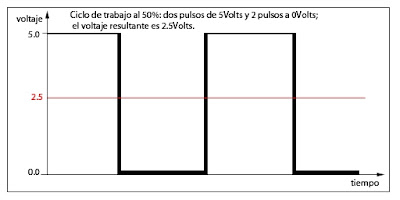
The components important control circuit is an integrated circuit and a MOSFET IRF NE555N 530. NE555N The integrated oscillator is a circuit that generates a square wave at its output. The frequency and duty cycle is controlled by resistors, capacitor and a potentiometer. The system used to regulate the voltage, is known as PWM (pulse width modulation for its acronym in English). This system is to generate pulses that are 0 to 5 Volts, so that by varying the amount of time it takes the pulse of 5 volts total voltage is controlled:
The integrated NE555N
is unable by itself to control the amount of current required in electrolysis process, it is used for another component called MOSFET which is a kind of electronic switch, which is activated when it receives a pulse circuit integrated. Each MOSFET has a capacity of 14 Amps. Putting several of these in parallel, one can multiply the total number of amps they can control. You must have a voltmeter connected to the electrodes so that the operator check how much voltage is applied during the recording process.
Another type of control circuit, a bit more complicated to assemble and more expensive, could allow the operator to program the amount of voltage to be used in the process and the etching time. It could also monitoring practice and record the resistance to the passage of current between the electrodes, temperature and other variables to consider within the research process.
The way to control the voltage is the same as using the most basic control circuit (PWM), but in this case would require a microcontroller and the PIC 16F873A and some other components as the data you want to collect in the etching process .
Another interesting possibility offered by the microcontroller, is working voltage regulation using different types of waves, not only square, which could lead to different results metal engraving.


0 comments:
Post a Comment